
Inductively coupled plasma mass spectrometry (ICP-MS) is a long-established and powerful analytical technique for identifying and quantifying the elemental composition of a sample. For solid samples it traditionally relies on digestion, followed by introduction of a homogeneous liquid phase sample extract to perform the analysis. This means that while it can very accurately and sensitively tell the user which elements are present and at what concentration, it’s completely unable to give any information about where the elements are located in the sample.
If spatial distribution information is required, it would be necessary to cut the sample into small pieces and separately digest each piece, followed by analysis with ICP-MS. The concentration data can then be re-assembled into a graphical representation of the elemental distribution. This approach would clearly be crude and very labour intensive, hence laser ablation, with its small beam size, precise control of the sample position and ability to directly introduce solid samples without the need for digestion has been used for “elemental imaging”.
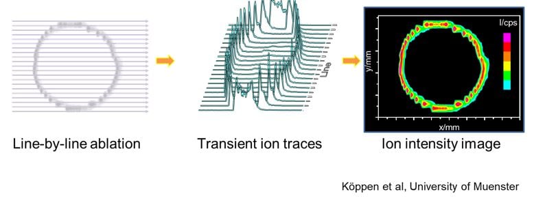
Until quite recently, however, it has been problematic to generate high quality images because of the speed and spatial resolution of the systems employed as well as the difficulty of turning the data into a useful image. The basic premise of LA-ICP-MS imaging is to move the area of sample to be imaged under a pulsed laser beam, ablating an area of sample with successive line scans. As the sample is moved, the ablated material is carried as an aerosol on a gas stream to the plasma mass spectrometer where elements of interest are measured. The signal intensity, as a function of time, can be correlated to a physical position on the sample surface and an image can be constructed (see Figure below).
The major issues are summarized below, along with some possible causes:
|
Issue |
Possible Cause |
| Slow speed of imaging | Slow washout of the sample chamber means that the sample must be moved slowly to avoid a lateral “blurring” effect. |
| Poor spatial resolution | Slow speed of washout of the sample chamber can cause lateral “blurring” if the sample is moved too quickly. Minimum laser beam diameter limits attainable resolution. |
| System optimization for imaging | Because the laser system and ICP-MS are separate instruments, one system needs to “trigger” the other and the parameters on both must be carefully selected so as not to have unsynchronized measurements. |
| Data-to-image conversion | The laser-sample position is not readily correlated with the time-resolved ICP-MS signal measurement. Several data correction routines (gas blank subtraction, quantification calculations, drift-correction) may be required and ICP-MS software packages rarely include these features for an imaging dataset. |
Recent advances from Ghent University have been commercialized by Teledyne Photon Machines and now offer an off-the-shelf solution to many of these issues.
Low Dispersion Sample Transport
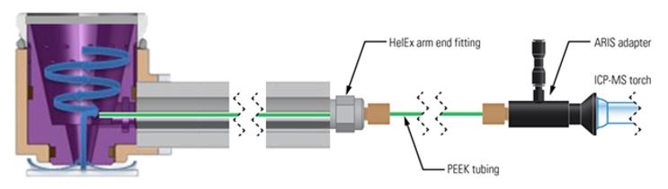
To maximize speed and lateral spatial resolution, it is essential to minimize the broadening of the pulses of aerosol generated by the laser. The Aerosol Rapid Introduction System (ARIS) is a simple adaptation to the HelEx II sample chamber that dramatically reduces aerosol dispersion, offering full pulse transmission in typically less than 30 milliseconds. By comparison, the full pulse transmission time for a typical single-volume sample chamber without low dispersion sample transport system could be up to three orders of magnitude slower. The figure below shows a schematic diagram of the HelEx II inner sample cup and ARIS low dispersion sample transport system.
To learn more about this technology, see http://www.teledynecetac.com/products/laser-ablation/aris.
Imaging-Specific Software
Hyper Dimensional Image Processing (HDIP) software provides a commercial solution to many issues relating to instrument and method optimization for elemental imaging. The software provides tools to enable optimization for laser and ICP-MS parameters, simplifying the generation of images with the best balance of resolution, mapping, and image contrast for every element. The software also hugely simplifies and automates the data reduction and image generation process without dumbing it down. These tools offer the user the ultimate in speed, quality and convenience for routine imaging.
For more information on HDIP software, visit http://www.teledynecetac.com/products/laser-ablation/hdip-imaging-software.
Example Images
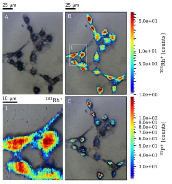
As an example of what current generation systems are now capable of is given in the figure below. Images of the 103Rh and 31P signal are overlaid on a brightfield microscopy image of the ablated zone prior to ablation. The images were generated with the ARIS system operating on a 193 nm Teledyne Photon Machines laser ablation system and data was processed with HDIP software. A) shows microscopic image acquired prior to ablation. B) is an overlay with the ‘jet’ colormap of the 103Rh
signal with an expanded view of the inset figure (1). C) shows an overlay with the ‘jet’ colormap of the 31P signal.
To see more about this application example, see http://www.teledynecetac.com/resourceSite/Application%20Notes/AP-AnalyteG2-003.pdf.
Conclusion
Latest generation laser ablation hardware technology and software now enables rapid and routine visualization of elemental spatial distribution down to the sub-micron level with greater speed, resolution and convenience than ever before. This extremely powerful technique is now commercially available now.